The Sonoff is a nice and cheap device, but since release v2 it’s more difficult to have it flashed to other firware then the default one. You need to solder an extra wire to a resistor and I failed 2 times at this part, so I need a different device that can do almost the same, also with ~230V input and output, can be controlled via wifi and is also kind of cheap.
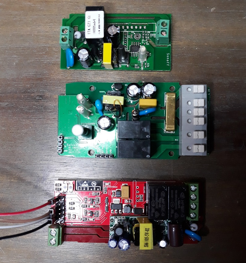
I ended my search with the “Wifi IoT Relay Board Based on ESP8266” from Electrodragon with the cost of ~6 euro (<7 US dollar). As a comparison between the Sonoff basic, the Sonoff Dual and the ElectroDragon (top-bottom), see the picture below (clickable):
Hardware features
- Based on ESP-12F ESP8266 Wifi Board
- This relay board use one AC input, and supports two relay AC output. Please note the output AC power comes/connected from/with input AC power. Relay only play as on/off switch for AC power. Will be danergerous to use in any other cases.
- Use mature AC-DC power module, input voltage 85 – 265VAC
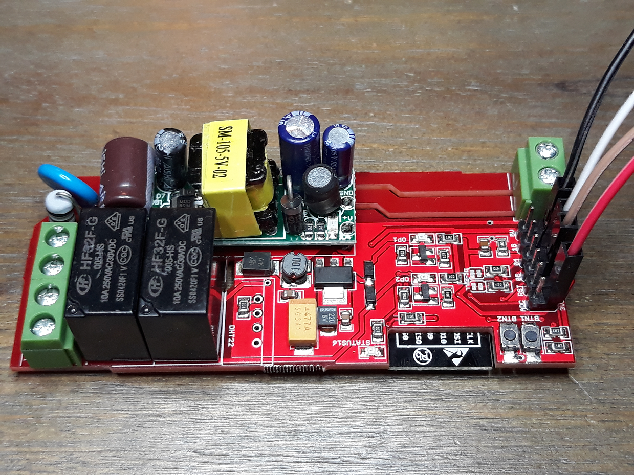
- Relay Specification: HF32F-G-5-HS, Common – open, 10A 250VAC, 30VDC, Control 5V
- Case general dimension is 111*42 mm.
- Two Lead out buttons BTN1 and BTN2
- Two relay indication LEDs
- One status LED, indicating connecting status in demo code
- A few lead out pins, from top (left) to bottom (right):
- Resevered design for temperature sensor DHT22
- Screw terminal which are easy for wiring output.
Pin mapping and connecting wires
I don’t want to use the existing software on the device, but want to use something like espeasy, for easy and better integration in my home automation setup. The release of my board is R1.9 2st_MAY (this is not a spelling mistake from my side…). The Nodemcu ESP-12F can have 4096 Kbytes of data. In case you upload any new firmware be aware of this.
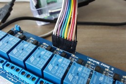
Next to the green AC input terminal, some header pins are available.

From left to right:
- Top row: ADC – RST – 05 – 04 – 15 – 5V
- Bottom row: 3.3 V – 14 – RXD – TXD – GND – GND
To flash the firmware, only the bottom row from the header pins is used. For flashing you need a 3.3Volt FTDI programmer, which is explained in the https://www.rutg3r.com/sonoff-firmware-tutorial-to-esp-easy/ post as well, you may use this tutorial as a reference for flashing the ElectroDragon to the Easpeasy firmware if you are not familair with the procedure.
Connect the 4 jumperwires as following:
| FTDI | ElectroDragon |
| 3V3 | 3V3 |
| TXD | RXD |
| RXD | TXD |
| GND | GND |
Before connecting the FTDI programmer to the computer, you have to press and hold down BTN2 on the ElectroDragon board. Even you have to hold down BTN2 untill flashing is finished!!
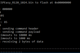
In my case I used the following firmware from Espeasy: ESPEasy_R147_4096.bin
In the end, connect a wireless device to the “esp_0” wifi access point. The wifi password = “espconfig”.
In the browser window, go to a random internet page, and the startpage the Espeasy configuration will be shown on the ElectroDragon device. Connect to your own wifi network and further configuration can be done from your own computer.
Espeasy configuration
For a referance, the following GPIO pins are used. As you can see,
| Function | GPIO |
| Relay 1 | GPIO 13, active high |
| Relay 2 | GPIO 12, active high |
| User led | GPIO 16, active high |
| Button 1 | GPIO 2 |
| Button 2 | GPIO 0 |
| DHT sensor | GPIO 14 |
Go to tab “Devices” to create a task to switch one of the relays.
Click “Edit” to create a new “device”, with type “Switch input”, with the following details:
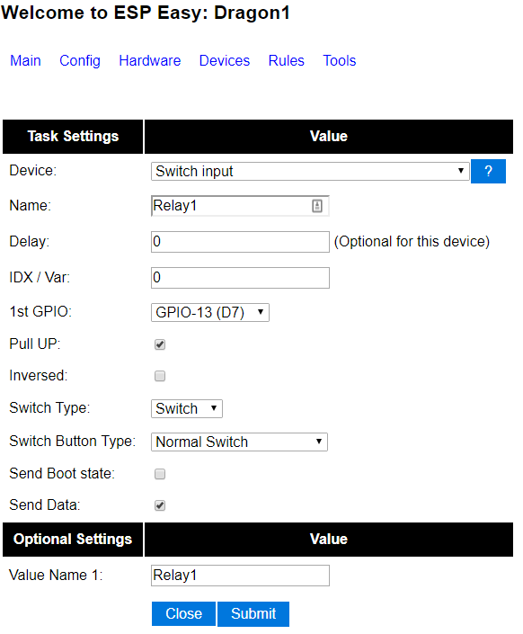
To save the input first, press “Submit”. To close this screen, click on “Close”.
Go to tab “Tools”, click “Advanced” and scroll to the bottom of the page and select the checkbox “Rules”. Now the “Rules” tab will appear in the top toolbar. Paste the following script code in the message screen:
On Relay1_On do
gpio,13,1
EndOn
On Relay1_Off do
gpio,13,0
EndOn
Press “Submit” to save the script code.
Based on the IP address (or hostname) of this ElectroDragon device, including the event name from the script code, you can control the created relay device.
http://<ip address>/control?cmd=event,Relay1_On
and
http://<ip address>/control?cmd=event,Relay1_Off
Test above commands in a browser. You will notice that the user led will be activated as well when the relay turned on.
Repeat above steps to create a device and rules for the other relay.

Hi Rutg3r
I have personalize the firmware and replace it by one simple TCP commands firmware. With it , i can activate , deactivate and activate during one time (define as parameter in the command). I use it to run animal feeder. Like this device is equipped with endless screw, i need to initiate it at start,and it’s more easy if you do that near device. For that, i have add two push buttons (one for each screw) who run the screw motor when you push on it. Those push buttons are connected on GPIO 4 and GPIO14.
i whish your curiosity is satisfy.
Regards
Eric
Thanks for your explanation.
But i have found one small error with this module. It seem than GPIO 04 and 05 are invert on schematic and printing board. the mistake seem become from ESP-12F pin declaration who are not correct.
Hi Eric,
Just curious, where do you use GPIO 04 and 05 for and what kind of devices are you controlling?